DATE: 01-14-2026 – TIME: 10:00 – 4:00 ~ 5:00
Today the goal was to complete the assembly of the firewall which is outlined in the drawings as FF-01 and FF-02. I was pleased to have a retired air force jet engine mechanic, engineer and Osprey crew join me in the building process, Jared.
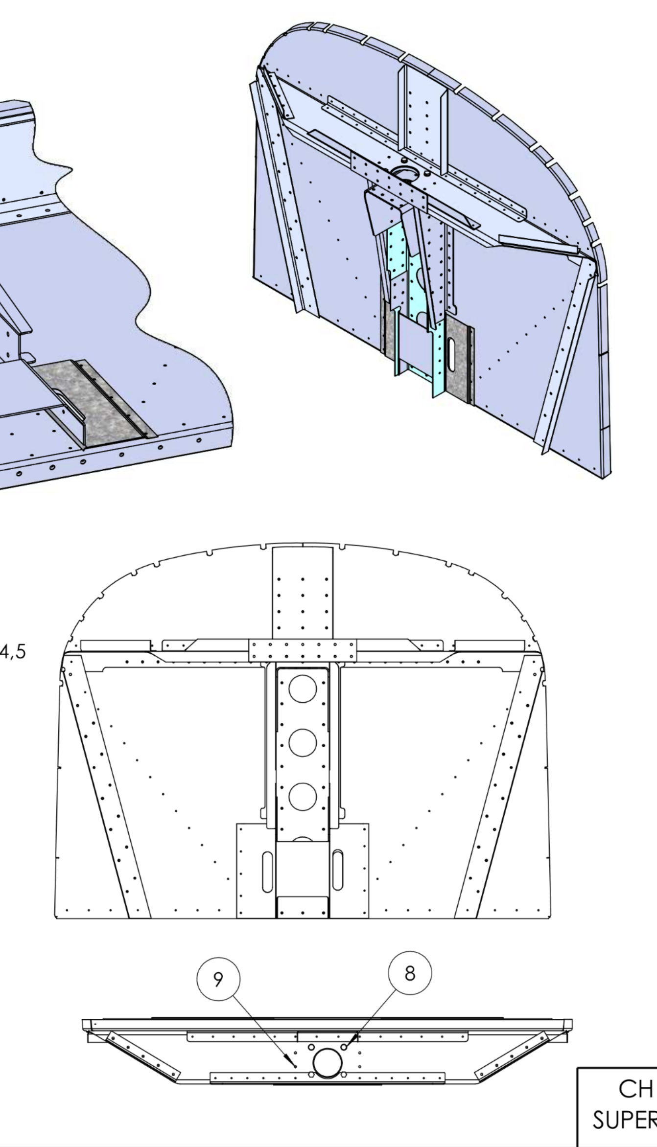
We first assembled all the various components from FF-01 and FF-02 onto the firewall SD75F40-4 with clecos. This required referring to LL-01 and LL-02 in addition to FF-02.
I decided to do this because there are parts on both sides of the galvanized firewall sheet and I did not want to end up having to drill out a bunch of rivets. As it happened we still managed to put some rivets in the wrong places and have to drill them out and replace them. Additionally, some of the holes were undersized and they had to be drilled out, particularly the bolt holes in the upper stop SD75L3-1 and the gear gussets SD75F40-13. The gear gusset flanges that get riveted to the C75F8-4 stiffener were not drilled. We left that drilling until the gussets had been riveted directly to the F40-4 firewall itself to make sure we drilled it correctly. These holes in the gusset flange into the stiffener are #12 for A6 rivets.
You really have to pay attention to the order in which you are riveting things together. Here are a couple of examples.
Don’t put rivets in the bottom 7 rivet holes gear gusset sides to the centre LS75F9-4 stiffener where the LS75F9-6 goes until you are ready to rivet the centre firewall doubler in place. Don’t put rivets in the firewall bottom stiffener, SD75F40-5, until you have the slide covers, C75F8-8 in place, and the LS75F8-10, diagonals, in place. Put another way, don’t rivet the last holes in the LS75F8-10 until you have the slide covers in place or you will be drilling them out.
Don’t rivet the C75F9-1, forward gusset, in place until you have riveted the LS75F9-8, firewall and stop stiffener and C75F9-7, upper firewall channel, in place because it will be difficult to pull the rivets from the front.
There is an instruction to pull rivets from the front, at least with elements on drawing FF-01. Where possible, I stuck to “standard practices” placing the manufactured head against the thinner material, and the shop head against the thicker. For me that meant placing the shop head on the galvanized firewall sheet.
All that said, the process is fairly straightforward, just pay attention to the overlaps and order. We had to drill out the bolt holes in the gear gussets for the AN3-5A bolts. We had already riveted them in place when we did this because we forgot. I recommend drilling them out before you rivet them to the firewall, on a drill press.
It may be that some of the holes we had to drill out were too small because of primer, not sure. You do want to check before you start assembling things though because it is far easier to drill to correct size before assembling.
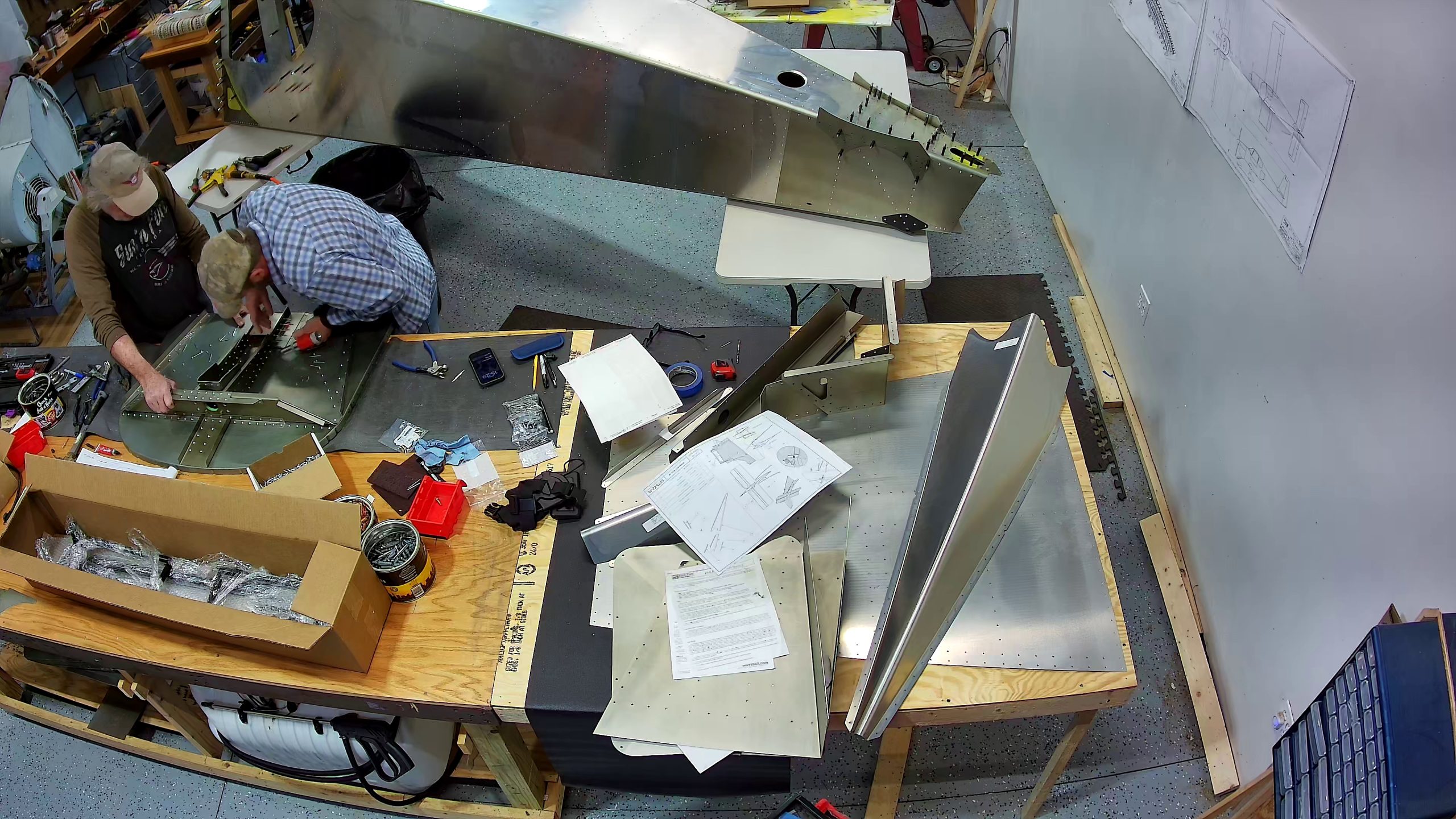
Here are various snapshots of the process. Unfortunately the location of the bench is not ideal for these photos but they are reasonable resolution so you can zoom in. I will be starting on the seats next and relocating the bench to make more space for extending the fuselage (and getting better shots of the front fuselage assembly process).


A couple of other notes worthy of mention.
- My copy of the printed drawings shows the stiffeners both overlapping the channel and being overlapped by the channel – per these drawings on pages FF-01 and FF-02:
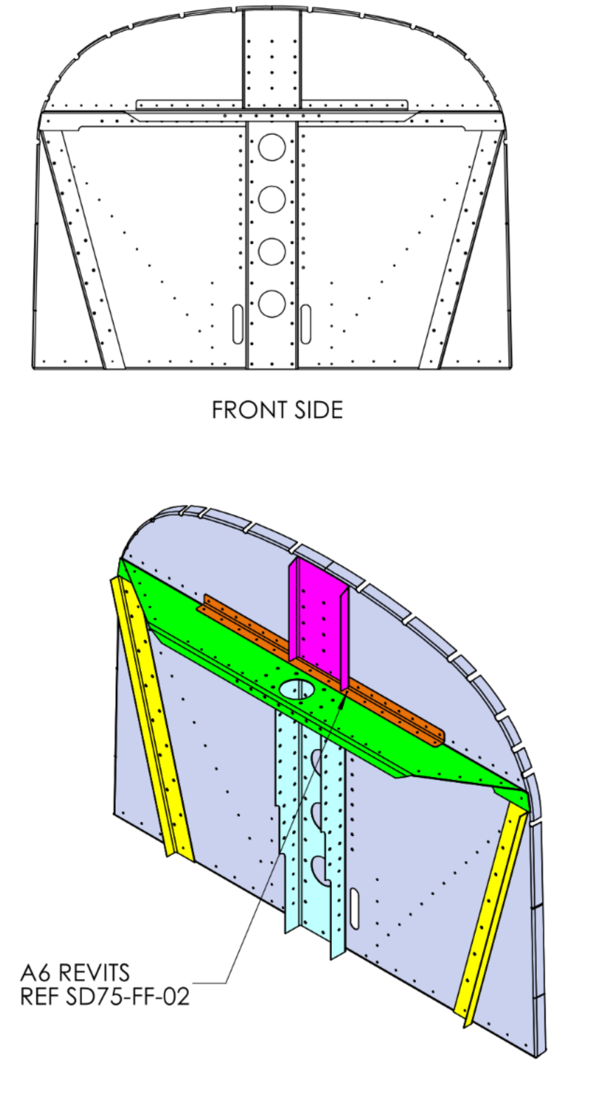
- The very top hole in the stiffeners, C75F8-3, which goes through the SD75F40-6 channel and the firewall itself is NOT a rivet hole, it’s a pilot hole for the 3/8 inch engine mount bolt. So don’t put a rivet in it.