DATE: 01-16-2025 – TIME: 01:27 – 4:00 ~ 2:30
We put the rudder and brake assembly aside and flipped over to page FF-05 to add the strengtheners and the channels to the LS75F10-3, cabin floor.
The cabin floor longerons in my kit had no holes drilled and no cut away at either the front or rear end. The printed diagram shows the cutaway sections. In fact the IPL sheet for FF-05 refers to the tapered end saying it should be at the rear.
We opened the solidworks EASM file to take a look at the assembly and then to use the measuring tool in solidworks to figure out the length of the taper. Once we had that done we clecod the longerons onto the cabin floor, marked the length of the tapers, and match drilled the holes through the skin. You have to be careful doing this because, apart from anything else, the skin is thin compared to the longeron and if you don’t get the drill bit in the centre of the skin hole, or it moves when you start drilling, you can enlarge the hole in the skin and end up with a hole off centre in the longeron. The IPL instructions say to start with drilling one hole, then cleco it, then drill every fifth hole and place a cleco, then do the remainder of the holes without adding any more clecos.
After removing the longerons from the cabin floor we tapered each end with the bandsaw and then cleaned up the tapers with a rasp and 3M smoothing wheel.
You also need to note that the rudder later bearing is bolted through the longeron so there are two holes that need to be drilled for AN3 bolts – that’s a #12 drill bit, rather than the #21 used to drill all the A5 rivets.


After that I tidied up the bench a bit, removed the rudder pedals from the rudder pedal channel, SD75F40-8, clecod it and riveted it to the heel support channel, SD75F40-9.
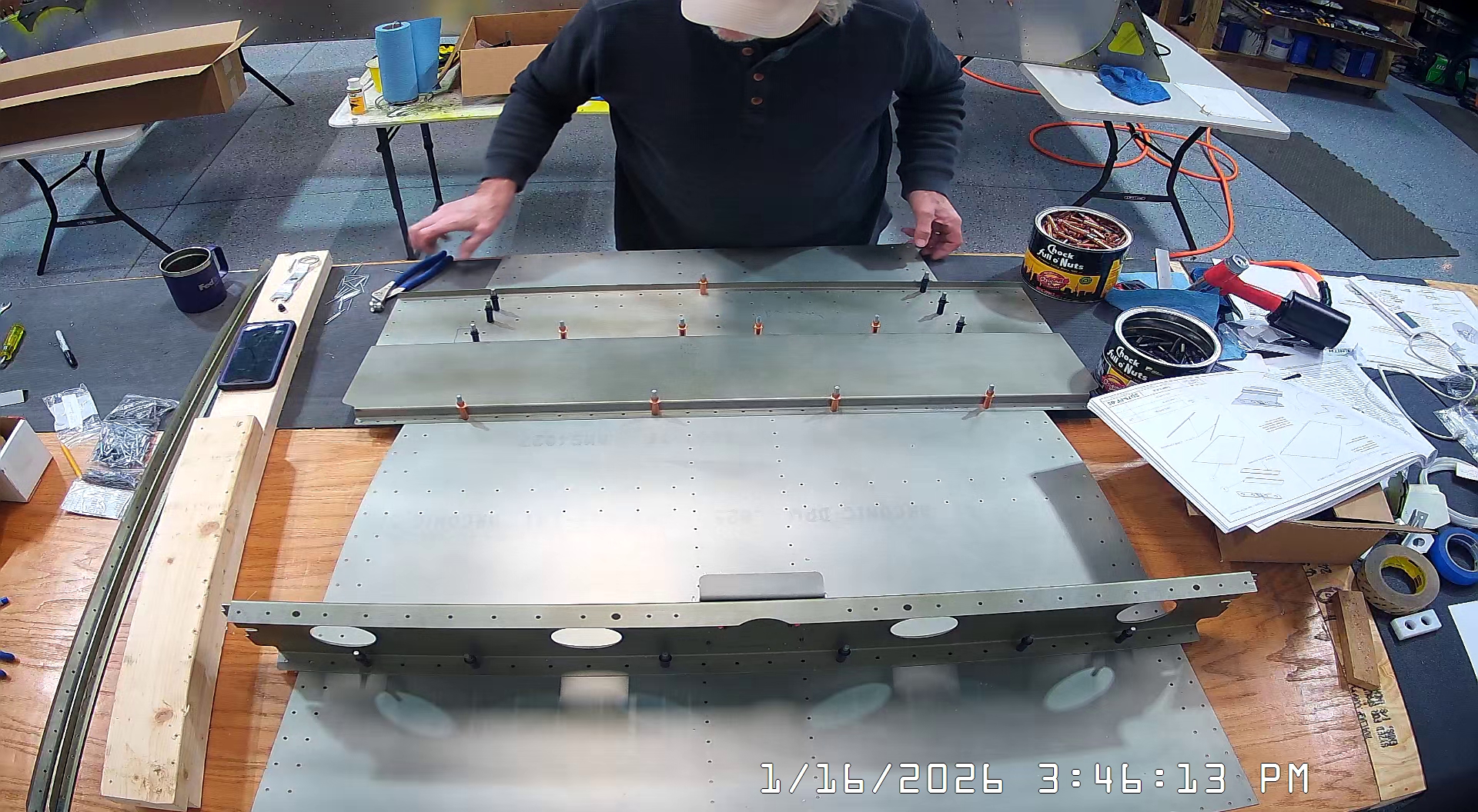
I then clecod the front seat channel to the cabin floor as well, per the instructions on IPL sheet FF-05.


Moving on to FF-06…