DATE: 01-23-2025 – TIME: 10:48 – 3:17 ~ 3:20
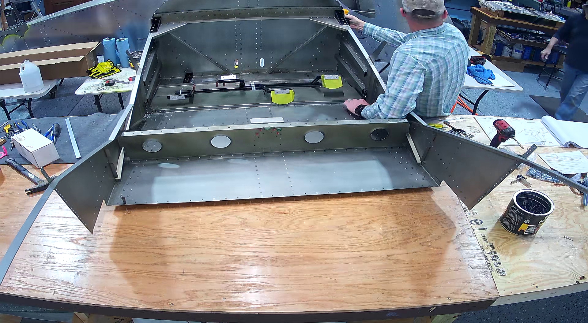
Continuing with the Zenith 750 SD build on page SD75-FF-10 we are installing the engine mount brackets and finishing off what we think is appropriate prior to attaching the forward fuselage to the rear.
As mentioned in the previous post, this is where we discovered that you have to leave the forward 3, outboard rivets when riveting the forward side skin floor, to accommodate the lower, left and right, engine mount brackets.
We also discovered that we had put rivets in the pilot holes for the 3/8 engine mount bolts at the top of the C75F8-3, firewall side stiffeners and had to drill them out.
The key with attaching the engine mount brackets is getting the face of the bracket flat and flush up against the firewall and then as much of the flange as you can along the top of the longerons so as to get maximum strength while not obstructing the skins. The top brackets are going to overhang the longerons on the inboard side, just make sure they are flush with the outside edge of the longeron, not the skin, to the extent possible.
The drawing specifies a distance of 8.14 which one presumes means mm although it’s not specified, the longeron being a 3/4″ extrusion. The problem with just measuring and drilling the longeron is that when you then place the mounting bracket in position you either have to mark the bracket from the underside, blind, or drill it from the underside, also blind. Then if you have drilled both holes perpendicular you will have a hard time getting bolts through both components.
What we did is we first clamped the bracket to the longeron so it was flush with the firewall and the most rearward point was flush with the outboard edge of the longeron. Then we drilled through the pilot hole in the firewall with an A5 (#21) drill bit. We then removed the bracket, marked a line down the inside of the bracket that gave use enough space for the bolt head and a socket against the outsided edge wall of the bracket (I think it was 7 mm). Then we drilled a hole in the centre of the bracket along that line, measured an inch (25mm) behind the centre hole, drilled the next hole, and an inch (25mm) forward of the centre hole and drilled the third hole. We then clecod the bracket to the firewall and drilled through the bracket into the longeron. Worked perfectly.
There is also a pilot hole in the lower firewall, that may look like a rivet hole, that will need to be drilled out for the 3/8th” engine mounting bolt. My kit was missing the right lower engine mounting bracket which Roger is shipping right away. The bad news is that the other 3 are powder coated (although it is suggested this is not a good practice because it makes cracks in the mounting brackers much harder to see).
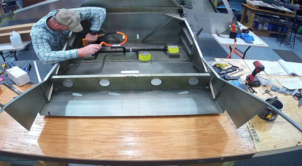
Here are the best snapshots I have of the process.


At this point there were still some rivet holes in the bottom of the cabin area that we had not noticed specified to be riveted and we did not know what size as the top skin was drilled while the bottom / cabin floor was not. We were not sure if the rivets should have been A4 or A5 as the rivets in the bottom seem to be some mix of A4s and A5s so we opted for A5. Better to have a larger than necessary rivet than one not large enough.
While Jared was finishing off those rivets I was making sure we were going to get some more by ordering some and letting Roger at Zenith know we were short. I actually counted all the holes that were A5 on one side of the whole fuselage and in the interior for a rough estimate.