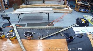
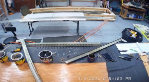
DATE: 09-09-2025 – TIME: 13:30 – 4:30 : 3:00
I sent a question to Zenith yesterday with respect to the correct rivet sizes for the HT frame and the V Brace (HT frame doubler) so thought I would continue with the rear wing attachment frame and bracket. This is on page SD75-FR-02 of the design drawings. As I create a new post for each section I will append a .# to the post.
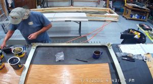
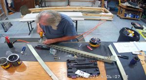
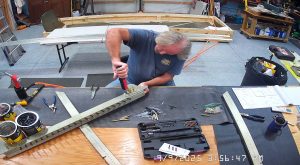
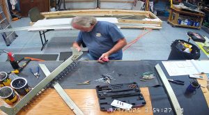
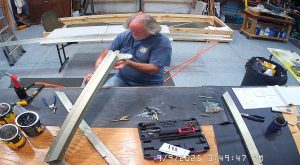
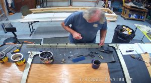
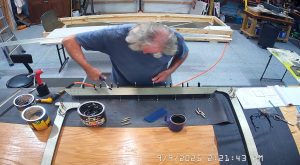
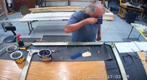
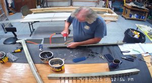
I started with the top channel, C75F3-3, and clecod the rear top channel, C75F3-4, and rear top channel angle, C75F3-6 together and put the rear wing brackets, SD75F4-4, in place on the front of the top channel so that I wouldn’t put rivets into the holes used to attach the rear wing, and then riveted the front, bottom and rear rivet lines with A5 rivets. The rivet holes in the front rivet line of the C75F3-3 are all drilled A5 (3/32nd) which is too small for the A6 rivets and the AN3-6A bolts called for in the drawings on page SD75-FR-02 where the rear wing brackets, SD75F4-4, are attached and will need to be drilled out with a #12 drill bit. In fact, possibly because of the priming, I had to “ream” out a lot of the A5 rivet holes in the front, bottom and rear with a #21 drill bit in order to avoid having to bash the rivets into the holes.
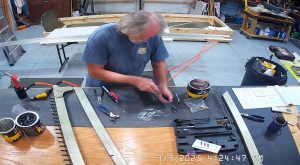
Once I had completed that process I switched to attaching the side channel doubler to the side channels.
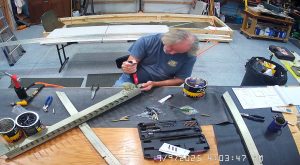
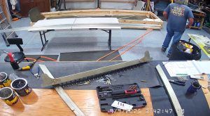
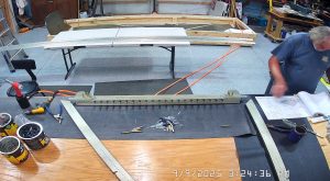
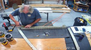
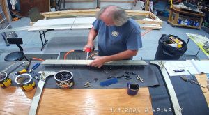
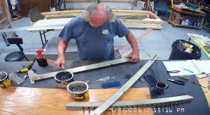
The SD75F6-6 doubler is inserted into the LS75F4-1 side channel such that the undrilled flange is toward the outside of the channel. Line up the holes in the doubler such that all the holes in the channel are aligned with all the holes in the doubler which will result in the doubler with the undrilled section of the drilled flange extending down toward the bottom of the side channel. This is shown in the photos below where you should be able to see the long tapered cut at the top and the short tapered cut at the bottom. The bottom section of the doubler and outer channel is drilled when assembling it with the rear super bracket SD75F36-5 per drawing SD75-FC-03.
At this stage I riveted the outer channel and outer channel doubler together with 26 * A5 rivets per side. Per best practices, I inserted the rivet manufactured head against the thinner of the two parts, in this case, the outer channel, and the shop head is formed against the doubler.
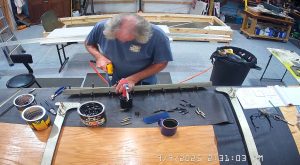
While the IPL sheet FR-2 refers to the SD75F4-4 and the attachment bolts AN3-6A it does not state specifically whether to attach the rear wing attachment to the front of the top channel C75F3-3 but I did this anyway, torqueing the bolts to 20-25 in/lb plus running friction. In my case this was between 32 and 25 in/lbs. FAA circular AC_43.13-1b is really helpful in this regard (figuring out the correct torque values).
Having completed torquing the bolts I dabbed each nut and bolt with some red torque marker and then inserted the A6 rivets into the remaining holes through the rear wing brackets and into the top channel. I did not get them riveted today but will do so tomorrow. It’s important NOT to rivet the side channels into the rear wing brackets as this is done later.