
DATE: 9-10-25 – TIME: 1:30 – 5:00 ~ 3:30
Today I began by finishing off riveting the rear wing attach brackets to the front of the top channel as I did not get it completed yesterday.


I then turned the page to F3-30 where the process of assembling the bottom skin and all of the stiffener angles are attached.
I didn’t pay too much attention to the instructions but I did find that I had sprayed the incorrect surface of the rear fuselage skin LS75F1-2 so I began by priming the top surface with zinc phosphate which I have in a few rattle cans. It’s bright yellow rather than a golden-green of the P60G2 so it will be easy to see where I made boo-boos later on.
I didn’t pay a whole lot of attention to the instructions, to tell the truth, as they are too “brief” to be of much use. I started by reviewing page SD75-FR-03 of the drawings and assembling all of the components on my bench. This was when I discovered that I had primed the wrong surface of the rear bottom skin, LS75F1-2, because the diagonal L angle is supposed to go left to right from the back, so I had to being by priming the inside surface. I have rattle cans of zinc phosphate specifically for these events.


So I laid out the forward skin with the inside up, not inverted as the IPL says, and lay the longerons, C75F2-2 on top. I initially clecod the longerons, laterals and diagonals from underneath – i.e. from the outside surface in – by lifting the sheet and the longerons. That way I could place everything easily and see what I was doing. Then I put clecos in from the top – from the inside surface.
After doing that, and again referring to the IPL, I decided I would rivet all the A4 holes in the longerons and then in the laterals and diagonals. I did get the longerons finished and some of the laterals and diagonals.
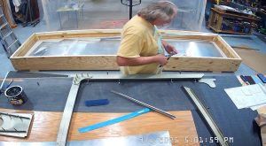


You will notice in some of the pics above that I am using a rivet puller. The IPL says to use A3 rivets to install the nutplates for the access panel. I decided to not do that because it would leave a gap between the cover and the fuselage and instead am dimpling the skin and the nutplates and using solid AN426AD3-3.5 flush rivets. This should give me a much nicer close fit between the cover panel and the skin. I also did this with the elevator trim actuator cover and will likely do so wherever there are cover plates. In order to do this, and because I am using a hand squeezer for the rivets, the SD75F19-1 Z channels need to be left off until after the nutplates are attached or squeezing the rivets will be very difficult, if not impossible.
One last item of note is that the SD75F19-1 Z channels had to be filed down at the end that overlays the SD75F19-2 in order to get them to lie flat against the lateral with pushing it rearward.
The IPL says to not rivet the A5 holes until later. It also says that the A5 holes extend from the front of the longerons back to the SD75F19-2 lateral Z angle. That’s partly true. The forward skin, LS75F1-1 is drilled A5 back to the lateral but neither the longeron nor the lateral is drilled A5, they are drilled A4, so I redrilled them A5. This is true for both sides.
Another problem exists with the rear bottom skin, LS75F1-2, where it overlaps the LS75F1-1 forward skin. There is a double row of A4 rivet holes in both skins extending from, and including, each longeron. The problem is that the hole closest to the aft edge on the forward skin lays upon the rear skin where there is no hole. To make matters worse, there is a hole in the aft skin essentially on the forward edge of where the hole in the aft skin needs to be. That’s not quite the extent of it though because the longeron doesn’t have a hole at all. While I have not done it yet, I will drill an A4 hole through the hole that has been CNC cut in the forward skin and then through the rear skin and the longeron. While the hole in the rear skin is going to be far too close to the hole that has been CNC cut, the rear skin is sandwiched between the forward skin and the longeron and the shop head will be up against the longeron and the factory head will be against the forward skin so this should be OK.
To me, these two errors are appalling. Not because of the fact that it presents a significant threat to the integrity, and therefore safety of the aircraft, but because after programming the CNC machine and cutting some parts, nobody bothered to cleco the parts together to make sure they were correct. That said, I could have got this wrong…