DATE: 12-24-25 – TIME: 2:15 – 4:43 ~ 2:30
Section / drawing FR-11 of the Zenith 750 SD fuselage build documentation is initially focused on the assembly of the rear armrest frames which also happen to enclose the flaperon linkages on the left and right of the fuselage. My kit came with a fair number of issues with the parts that were not consistent with either the printed or solidworks drawings. I’m going to just outline them here at the start in case you have similar issues.
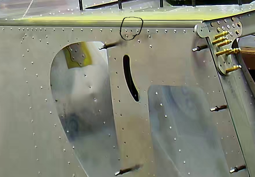
First, in section FR-09, you are completing riveting the top skin to to longerons after having riveted the shoulder harnesses in place. On the left side of the fuselage there is no shoulder harness bracket so I riveted the longeron in place as instructed. However, there is one rivet that you have to leave out, and also have to leave out on the right side – where it goes through the shoulder harness bracket as well – because the flaperon cover is riveted there.
This snapshot is of the right hand side where the rivet also goes through the shoulder harness, but the same rivet on the other side should not be place until the flaperon control cover is riveted into place.
As far as the arm rests go, with my kit, these parts came with holes either not drilled at all, or drilled to the wrong size:
- SD75F31-2 – All the holes were in the correct location but apart from the nutplate holder holes which are drilled for A3, 3/32nd rivets, none of them were the correct size. I drilled out all of the holes that are spec’d for A5 rivets with a #21 drill bit and all of the screw holes with a #12 bit.
- SD75F31-4 – The arm rest rear corner brace came with holes in the flange that fits up against the SD75F31-2 arm rest frame. I drilled the holes out that needed to be #21 for the A5 rivets and the screw holes to #12. The other flange needs 6 A5 holes at the top that were not drilled, to rivet it to the SD75F32-1 baggage back gussets (which do have holes in them). Rather than struggling to drill through the baggage back gusset and into the SD75F31-4 I clecod the right frame in place with a narrow spare piece of aluminum I had predrilled the width of the F31-1 arm rest top and to the SD75F34-1, jump seat front channel, marked the holes in the undrilled flange of the SD75F31-4, removed it all, clamped right SD75F31-4 to the left and drilled through both where I had marked the right rear corner bracket. This corner bracket also has a flange on the bottom that is riveted, with 2 * A5 rivets, to the rear jump seat channel. Neither the flange of the rear bracket nor the rear jump seat channel was drilled for these rivets so again, after clecoing in place to get proper alignment, I will drill these holes with a 12″ #21 drill bit, through both the rear bracket and the rear jump seat channel at the same time.
- SD75F31-5 – The arm rest front corner brace came with holes drilled to attach it to the SD75F31-2 arm rest frame but not for the SD75F31-1 arm rest top and front. I will drill these out when it comes time to rivet the SD75F31-1 in place and I have it already clecod and / or partially riveted.
- SD75F31-1 – The arm rest top and front were drilled for pretty much everything except the A5 rivets that go into the baggage back / baggage back lower channel, the flaperon control cover, SD75F3-2, flange (which is drilled A4), and the flange that should be drilled A5 for riveting to the side skin. Also of note, the printed drawing shows 2 rows of rivets, A5, into the baggage back. The solidworks drawings show none, so far as I can see. Furthermore, on page FR-06, where you are assembling the baggage back it says to not rivet the bottom row of A5 and refer to FR-11. Well I did that, but when it comes time to aligning things, it is the 2nd to last row of A5 rivets where you need to leave the rivets out because the arm rest top and front, when in place against the baggage back with the arm rest frame in place, does not extend over the last row of rivets in the baggage back gusset and bottom channel.
- SD75F31-6 and 7 – The arm rest side angles, rear and front, are drilled A4 for the side skin and they need to be drilled out to A5, and are not drilled for the arm rest top and front, SD75F31-1, so they need to be marked and drilled to A5.
- SD75F31-3 – The arm rest side cover comes drilled too small for the screws so the holes need to be drilled out with a #12 drill bit to properly accommodate the flange on the AN525-10R7 screws.
I made the decision to not use the A3 and A5 rivets provided by Zenith, as “flush” rivets but instead to use AN426AD3-3.4, AN426AD3-4 and AD426AD5-5 rivets. These are “hard” solid rivets and provide a better finish and in fact are stronger than the blind rivets provided.
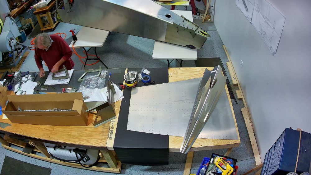
Here are snapshots from today.


I have been taking my time over the holiday here to do this section. I have assembled, disassembled and re-assembled the arm rest components multiple times to make sure I understand how they go together and exactly which holes need drilling, drilling out, and dimpling. I also had to get Roger at Zenith to send me the correct nutplates, which he did quickly, and said their pick lists / inventory for partial kits was being updated.