DATE: 01-20-2025 – TIME: 3:00 – 4:30 ~ 1:30
SD75-FF-09 is where we start the final assembly of the fuselage sub-assemblies before attaching the fuselage front, which is effectively the cabin and firewall, to the fuselage rear. The drawings on FF-08, FF-07 and FF-09 show things like the tunnel and the rear seat channel in place but there is no mention of riveting them in on the IPL or the drawings, so at this point we have not done any of that.
As of today, I am pretty low on A5 rivets, I think down to 40, whereas I still have about 2,700 A4 rivets. Roger tells me he has had the pick sheet changed for the future and has sent another 500 x A5. Once I have finished attaching the front fuselage to the rear I will count how many I still need (if any) and provide Roger with a close estimate of how many A5s it actually takes. Ditto the A4s which seem to be vastly overestimated, and the A6s.
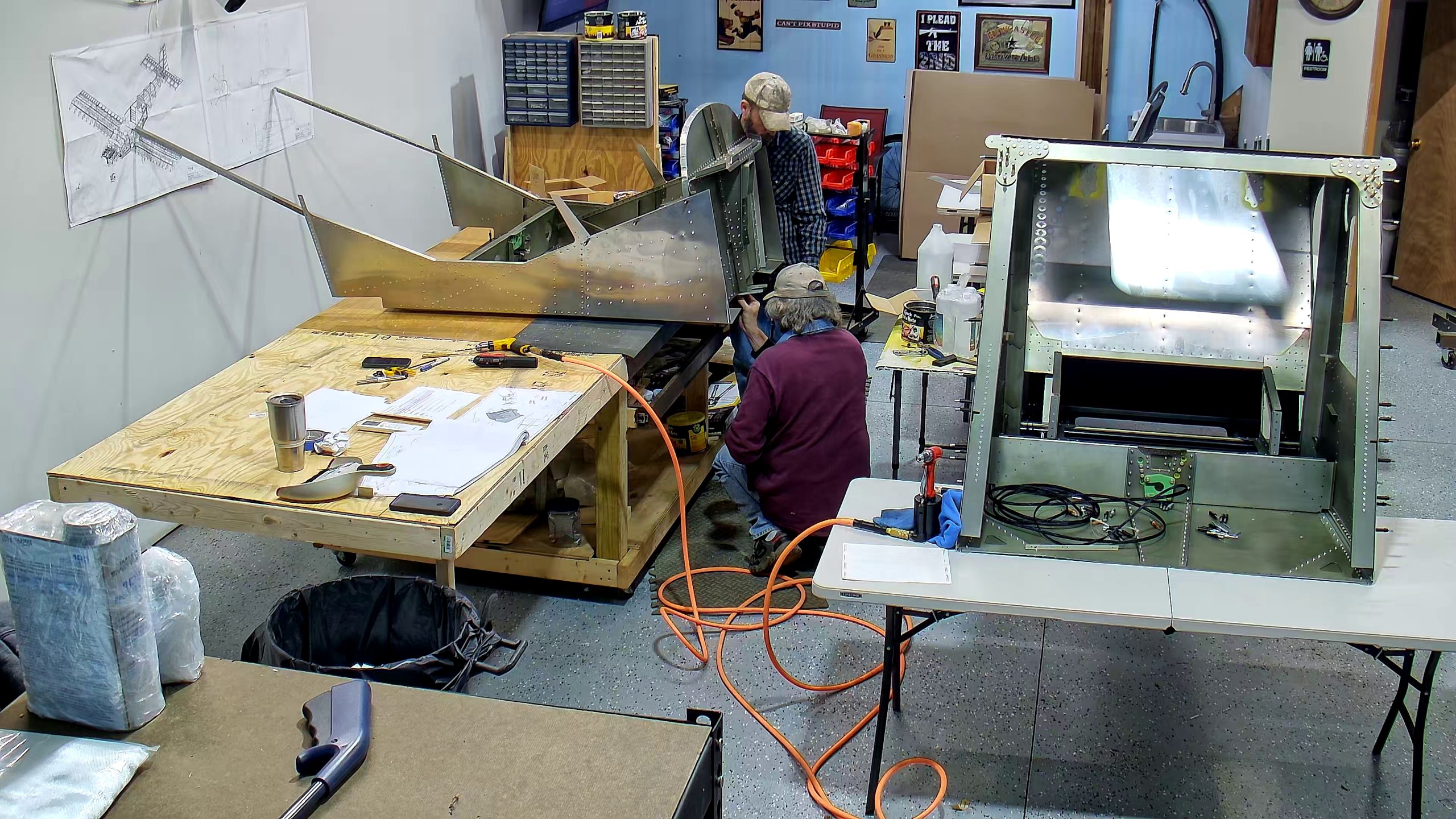
Meantime…you will see from the pictures that we started installing the firewall into to the front fuselage. It was at this point that we became aware that the drawings show the stiffeners on the front of the firewall as being both under, and over, the C75F8-4, top firewall stiffener. More about that in my earlier post.
You will see that we do not have the rudder pedals and brake cylinders in place even though the diagrams show them. It’s just easier working on the firewall without them in the way.
This is also where we discover that the lower engine mounting brackets need to be riveted at the same time as you rivet the front three, inboard holes for the cabin front sides. More on that in this earlier post.
We riveted the side stiffeners in place first. For my kit, only one row of holes in each of the SD75F40-2 and SD75F40-3 flanges was pre-drilled but that was enough to cleco in place and drill the remainder. We clecod and then riveted the one row of holes in each, the drilled one hole in the other flange in each, riveted it, then did a second hole in the middle of the stiffener and the one at the end and then rolled back and filled in. Note also that the stiffener overlaps where the front side skin overlaps the pre-assembled cabin frame so when you are riveting the side skin, if you are, ahead of time, don’t rivet where the stiffeners overlap.
The drawing shows that the firewall is at an 80 degree angle with the floor. Mine came pre-drilled so I expect the angle is correct.
The SD75F40-7, upper engine mount gusset in my kit was not predrilled, nor were the longerons and channel on the firewall for the gusset. Ideally you would have a 12 inch drill bit (#21) for A5 rivets because otherwise you might have the drill chuck banging up against the top firewall stiffener on the rear of the firewall.
The drawings showing the gussets, especially the solidworks drawings, are confusing because they show the left gusset upside down and beneath the flange of the firewall stiffener, which is not correct. Just refer to the right gusset, which is correct.


Here are some additional snapshots from a couple of different angles. These images are mostly 5M images so should zoomable.


