DATE: 03-31-26 – TIME: 9:10 – 4:40 ~ 6:00
Well, it’s been a long delay since stopping at the end of January. Partly because of lack of rivets but primarily also due to being heavily engaged in pruning the orchard and subsequent cleaning up.
I did not put the FF drawing pages in the title because we were doing different sections all over the manual as a consequence of catching up as hardware arrived.
As we went through this process I wanted to put washers underneath the bolt head and the nut where proper thread exposure allowed. Some of the bolts did not appear to be that well spec’d to allow for FAA best practices.
As of this morning, the cabin was clecod in place to the front of the rear fuselage so the process of final alignment and riveting was the next step. Plus, I had received the master brake cylinder so that I could finish off installing the pilot side (left) pedals. It turns out the brackets for holding the master cylinder are the same width apart as the slave cylinders. The master cylinders do not come with the controls, or the fuselage, but with the finishing kit, but if you order the dual brake option then you can use the slave cylinders to properly locate the master cylinder brackets.
We also found, during the installation of the engine mount brackets, that the lower left engine mount was missing. This necessitated getting one from Zenith and then having it powder coated, which caused a further week delay.
I also had to wait for A5 rivets. Initially, when ordering the fuselage kit, I received 2900 A4 rivets and 1200 A5 rivets. I initially bought 200 more and Roger sent me another 300 from Zenith, gratis.
SD75-FF-10
Anyway, today we started with the installation of the right engine mounting bracket which comes with no holes drilled for either the engine mount bolt (3/8th) nor the bolt holes to bolt to the floor. One of the oddities of the mounting brackets is that Zenith specs a countersunk screw for the forward “bolt”, while the bracket itself is not drilled, nor countersunk, because otherwise there isn’t enough space for the 3/8th engine mount bolt. By the way, this is also true for the upper engine mounts too. It isn’t possible to get a countersink into the bracket to countersink the hole after it’s drilled either because it is too far forward against the face of the bracket.
The floor of the cabin and the firewall do have holes for the bolts so the way we installed the bracket was to locate the centre front of the bracket and place it in line with the hole in the firewall, then drilled that hole with a #20 bit, clecod it in place, and then drilled the three holes into the base of the bracket from beneath the floor.
The easiest way to drill through the steel, and most accurate for me, is to start with a really small bit, I think we used a 1/16th or less, which goes through the steel much faster than, say a #20 or #12. Then drill the holes with the correct size bit.
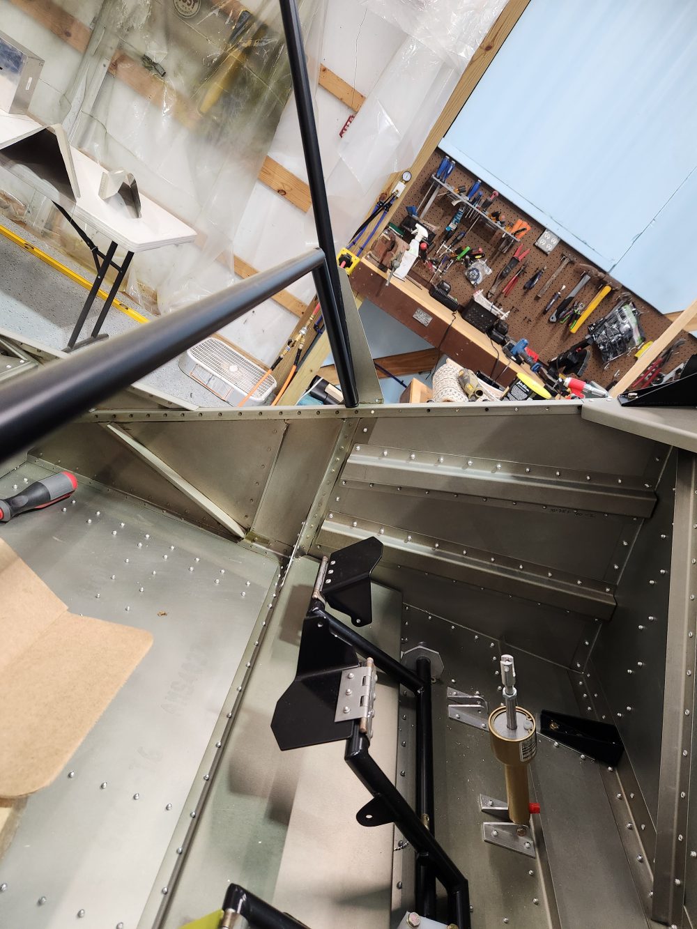
I have placed some photos here but you really can’t see much because the cameras are not in a good place for the work inside the cabin. I took some photos with my cell phone, after the fact.


After finishing the engine mount installation we continued with the fitting of the brake master cylinder vertical bracket installation on the left (pilot) side.
SD75-FF-04
There doesn’t seem to be an easy way to ensure that the left and right supports for the master cylinder are well placed. It just takes careful alignment and drilling.
When I purchased the fuselage I also ordered the dual brakes option. The kit came with the slave cylinders but not the master cylinders. That isn’t an issue if you know that the master cylinder mounting is essentially the same as the slave cylinder mounting and width, which I did not, so I purchased one of the master cylinders. Apparently the master cylinders come as part of the finishing kit.


The above images are large so if necessary you can zoom in to any section, or download them and zoom in.
Once the master brake cylinder mounts were all in place we attached the pilot’s rudder pedals to the rudder torque tubes.
Again, it’s difficult to see what is going on here. The rudder pedals themselves come without any predrilled holes apart from the brake cylinder attachment point. Then we attached the steel hinges first to the pedal, then aligned the pedal and hinge with the brake and torque tube and drilled and riveted the pedal to the tube.


At this point we moved on to figuring out how to attach the landing gear mounts to the fuselage which would entail making sure the front, cabin area, and rear fuselage were properly aligned and attached. Up until this point the front fuselage and cabin area were clecod to the rear.


Before we could attach the landing gear brackets we decided we should rivet everything else into place, i.e. the forward and rear fuselages to make them one piece, which also meant riveting the gear channel in place. There did not seem to be any instruction anywhere as to when one might do that, but this seemed like a good time.
At this point, it turned out also that the lower rear fuselage longerons, which were not cut to size, were too long and interfered with the placement of the gear mounting brackets. I had previously trimmed the longerons but not adequately. You can see in the slider above that I used a vibrating tool to trim the longerons and it worked well. I would suggest doing this when you first rivet the skins to the longerons as they effectively conform to the shape of the side and bottom skins.
So, after installing and riveting the gear channel and assembly into place we continued with riveting other components to make sure we had as accurate an alignment as possible. Clecos are great and make the whole process a lot easier, but they do not hold parts in alignment the way rivets do. Close, but no cigar.
SD-75-FC-01 to 04
At this point we were still riveting the primary parts together so that when we installed the landing gear mounts everything would already be aligned.
The tunnel sides, LS75F33-4, which are shown on the FC-04 drawing page with rivet holes, came with just one rivet hole drilled. The photos provided with the drawings don’t show rivet holes for the rear tunnel cover, SD75F33-5, the photos show locations for 4 nutplates and screws. At some point this was changed to rivets. I checked with Zenith and was informed that it is OK to user screws and nutplates so I purchased them as I already have solid, flush, rivets (AN426) and will dimple the rivet holes to get them flush.
Also, the tunnel sides rivet to the tunnel floor so you have to make sure there won’t be anything obstructing the installation.
There were no rivet holes in the side skins for the top cover anyway, we used a rivet fence to mark them. Sadly, this means I have to put a row of 9 nutplates and screws on each side of the rear cover. At least it won’t rattle.
We also dimpled the forward cover nutplate holding rivets and opted for the flush rivets I had to rivet them in place.


As I am typing this I am remembering having to drill out some rivets in the floor because they were in the way of installing the tunnel sides. I am not 100% certain this was the case but it’s worth noting if you want to minimize duplicating the problem.
Continuing on with drilling holes to matched size – quite a number of the holes in the skins and frame components were of different sizes and had to be drilled out to accommodate the correct rivets – mostly A5. The images in the following slider are related to riveting the seat frames (not sliders) in place.


At this point we are considering what is best to do next but essentially, after much drawing review, continued inserting rivets into parts that would provide better rigidity and alignment to the fuselage.
I am just providing a sample of the snapshots from the rest of the day.


At the end of the day, we had pulled a lot of rivets into the front and rear fuselage including the gussets and the rear wing attach points.