DATE: 01-02-2026 – TIME: 2:47 – 4:23 ~ 1:35
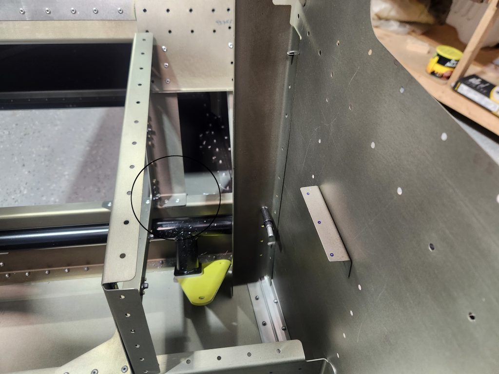
With the arm rest frames completed, the next step was to rivet them in place to the front and rear jump seat channels. Before I did that, however, I had opted to drill out a row of rivets that I had inserted in the baggage back. The baggage back assembly instructions say to leave the last row of rivets out. Here is a picture with the “last row of rivets out”./

Unfortunately, that’s the wrong row of rivets because those rivets are below the flange of the arm rest cover. The row of rivets above the row of clecos is where the arm rest cover should be riveted so I had to drill those 6 rivets out. See the snapshot below.

There is another error in the instructions provided in the IPL sheet. At least, it’s an error in my view.
The IPL sheet refers you to photo 2b of the arm rest frame where it is riveted to the jump seat rear channel. This photo shows the rear corner brace of the frame with the lower flange that gets riveted to the rear jump seat channel underneath the flange of the rear channel. Incidentally, my kit components came with no holes drilled in the channel or the rear corner brace.
When I tried to fit the arm rest frame onto the rear and front jump seat channels with the rear corner brace flange underneath the rear jump seat channel flange it place a lot of stress on all the parts and in fact distorted the rear corner brace. It did not look correct to me so I checked the solidworks drawing and the printed drawings. Both of those drawings show the arm rest rear corner brace on top of the rear jump seat channel, so that is how I riveted it in place.


I will take a couple of additional photos to better show the way I have riveted the arm rest frames in place as these photos don’t really show the setup very well.
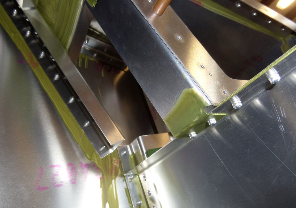
Here are a couple of photos that show the difference between the way I installed the arm rest frame and the way Zenith show it in their photo (but not the diagrams).
This is photo 2b from the Zenith files provided as part of the instructions and referred to in IPL FR-11.
Here is the printed drawing (Roger said always use the printed drawing as the definitive answer).
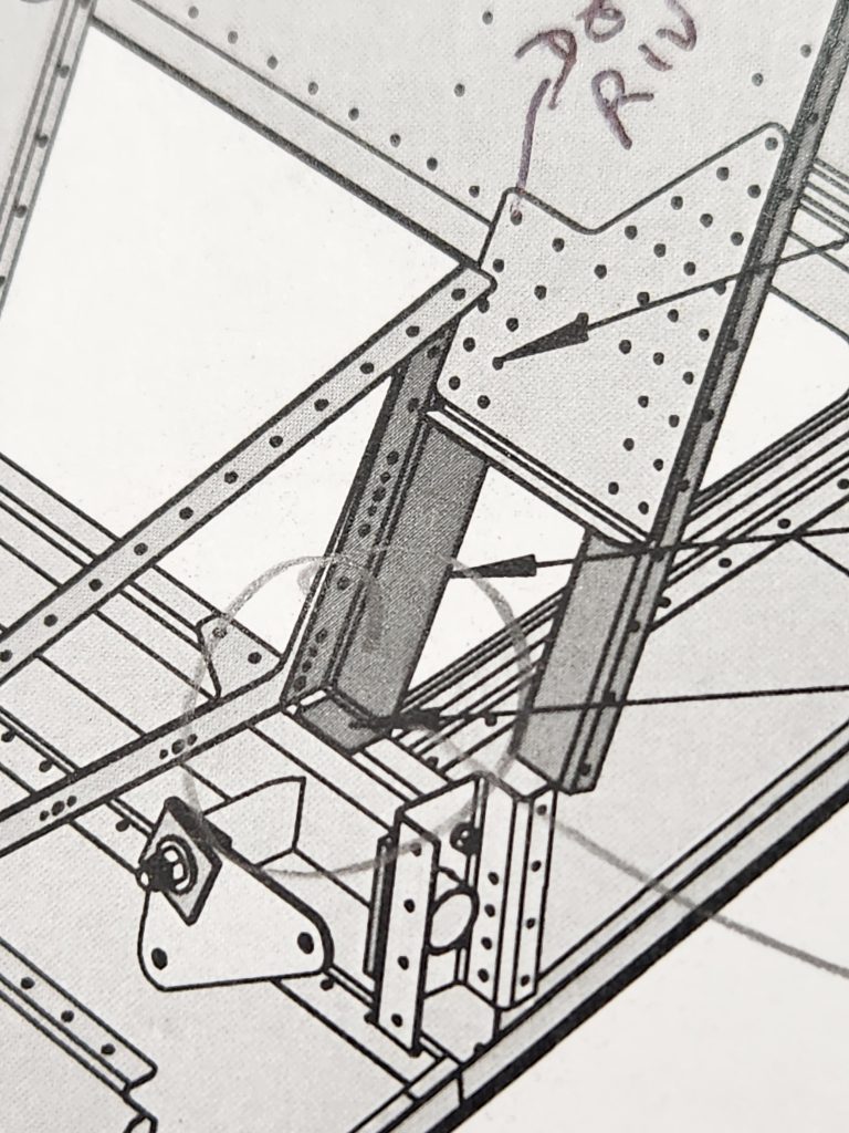
Here is a screen shot from the SolidWorks drawing:
Well OK, it’s coming. Apparently SolidWorks will no longer provide eDrawings for Windows 10. I never liked the way Dassault Systems ran their company. Not from the obscene prices they charged for their software nor the heavy handed way they policed their users.
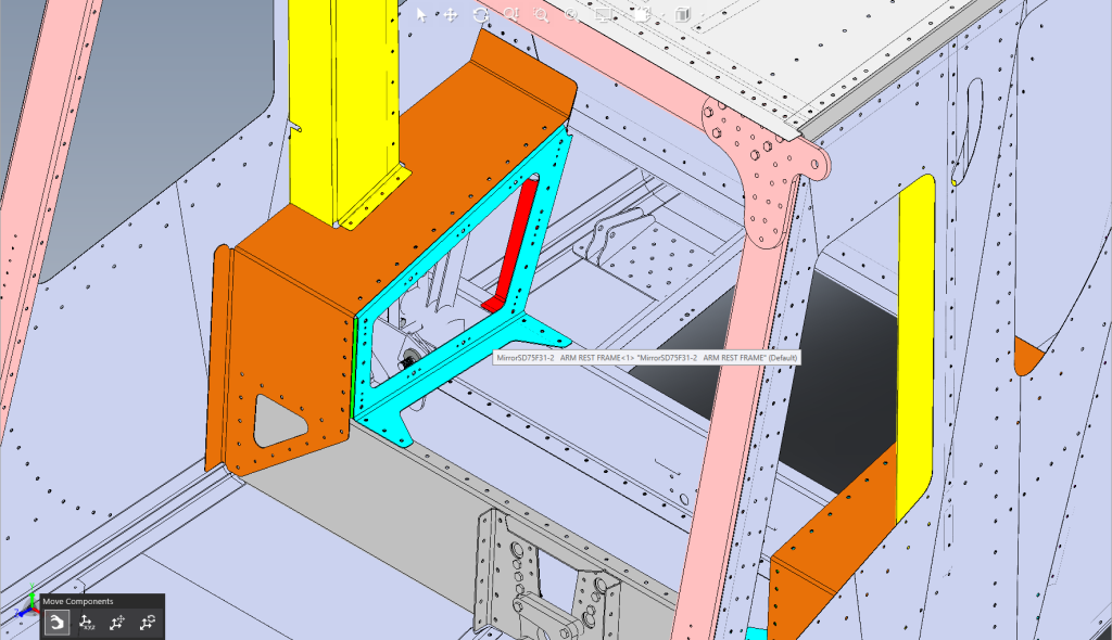
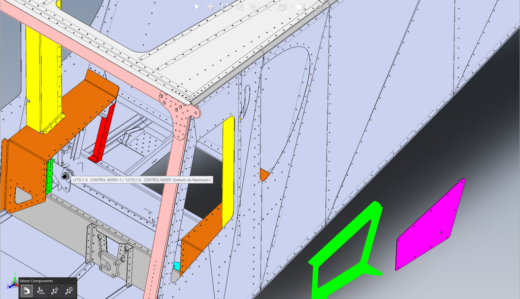
The red in the solidworks drawing is the arm rest frame rear corner brace and it is clearly show above (on top of) the read baggage channel.