DATE: 01-15-2025 – TIME: 10:57 – 04:30 ~
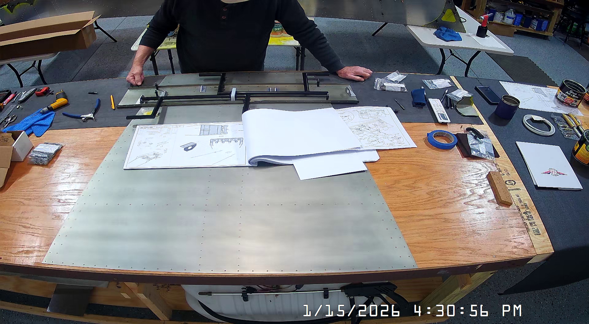
I started today with the assembly of the Zenith 750 SD rudder and brake pedals. As mentioned, I still did not have the brake master cylinders so it was not possible to lay out and mark the master cylinder brake supports but because I had the slave cylinders, dual brake option, we were able to do lay them up for assembly.


Setting up the placement of the rudder pedal lateral bearings, and for that matter the brake cylinder supports, is not an easy task as the bearings (and supports) do not have any bolt or rivet holes, respectively, just the bearing holes.
It’s not too bad for the bearings, so long as you get the bearing mostly in line with the centre bearing, but it is difficult to align, clamp and drill so we aligned, then drilled the bases of lateral bearings. Fortunately we were pretty much where we had to be to allow free rudder pedal movement.
When drilling the bolt holes for the lateral bearings and the rivet holes for the dual brake cylinders you also have to drill the skin as the holes in the skin are too small.
At this point, we put the rudder assembly aside because we did not have the master cylinders, so we left the brake pedals and steel piano hinges not attached to the rudder pedals and the slave cylinder supports not drilled.
It would probably have been better to not have the skins drilled where the brake cylinder supports go because then one could just use transfer tape or something to hold them in place with the brake cylinder attached to the toe brake plate and drill through both the brake support and the skin beneath instead of trying to line up the brake support with the holes in the skin.